2. HDLC Protocol Description
HDLC [High-level Data Link Control] là một bộ giao thức dùng để truyền nhận đồng bộ các gói tin trên các tuyến kết nối point-to-point. HDLC đóng dữ liệu thành các frames. HDLC hoạt động ở layer 2 của mô hình OSI - Data Link layer.
General HDLC Frame

General HDLC Frame
Opening Flag, 8 bits [01111110], [7E hex]
Address, 8 bits [ could be more]
Control, 8 bits, or 16 bits
Data [Payload], Thay đổi, có thể không dùng trong một số frame
CRC, 16 bits, or 32 bits
Closing Flag, 8 bits [01111110], [7E hex]
User data which contains 7E is resolved using an escape sequence which converts 7E to 7D-5E [with 7D being the escape character]. If 7D is used in the data stream it again is converted into 7D-5D. Address 11111111 is known as all stations, 00000000 is this station.
Frames may be aborted by sending an abort sequence [01111111] instead of the normal flag sequence [01111110]. An abort sequence will cause the frame to be discarded. During idle times when no frames are being transmitted idle flags [11111111] may be sent to fill the area between frames. A continuous series of flags [01111110] may be sent to fill the area between frames instead of sending idle flags [11111111].

Fill between Frames
HDLC Opening Flag
8 bits [01111110], [7E hex]
The Opening flag may be preceded by additional flags [01111110] or idle flags [11111111], both used as inter-frame fill.

HDLC Address Field
HDLC Address Field
The length of the address field depends on the data link layer protocol used, but is normally 0, 8 or 16 bits in length. In many cases the address field is typically just a single byte, but an Extended Address [EA] bit may be used allowing for multi-byte addresses. A one residing in the LSB bit indicates [the end of the field] that the length of the address field will be 8 bits long. A zero in this bit location [now the first byte of a multi-byte field] indicates the continuation of the field [adding 8 additional bits]. The SDLC protocol will use only an 8 bit address. The SS7 protocol, which is used in point-to-point links, does not use an address field at all.
The first [MSB] bit in the Address field indicates if the frame is a unicast or multi-cast message. A zero in the MSB bit location indicates a unicast message; the remaining bits indicate the destination node address. A one in the MSB bit location indicates multicast message, the remaining bits indicate the group address.
HDLC Control Field
The Control field is 8 or 16 bits and defines the frame type; Control or Data. The Control field is protocol dependent.
HDLC Data Field
The Data field may vary in length depending upon the protocol using the frame. Layer 3 frames are carried in the data field.
HDLC FCS Field
FCS [16 bits] = X16 + X12 + X5 + 1
FCS [32 bits] = X32 + X26 + X23 + X22 + X16 + X12 + X11 + X10 + X8 + X7 + X5 + X4 + X2 + X + 1
Frame Encapsulation:
A few different versions of the HDLC frame are shown below. These include the PPP [Point-to-Point Protocol] HDLC frame, and the Ethernet HDLC frame.

Ethernet HDLC Frame Encapsulation
Ethernet Frame Encapsulation:
The Preamble [a specific bit pattern] Informs the receiving station that a new packet is arriving and synchronizes the receive clock with the transmitted clock. Used in Ethernet, not HDLC.
The Address Field consists of a Source Address and/or a Destination Address. The Source and Destination Addresses identify the sender [Source] and receiver [Destination]. The Source Address is used to identify to the network that's sending data. The Destination Address is used to identify who should be receiving the data. Some protocols may only have one address.
The Control Field indicates the type of Information that is being sent as Data. It identifies the purpose of the packet as Data or Control information, and may also indicate the size of the packet and Data.
The Data Field is the actual information being transmitted. It can contain Control Information for handshaking, or actual Data used by applications.
The CRC [Cyclic Redundancy Checking] or FCS [Frame Check Sequence] contains an error checking number that the Destination can use to verify that the packet is error free.
The End Frame Delimiter has a specific bit pattern. This bit pattern identifies the end of the packet to the Destination. Protocols with fixed packet size may not require an End Frame Delimiter.
For some physical interfaces [SDH or SONET] after the data as been encapsulated into the frame it must still be scrambled before being sent to the physical layer [from the Link layer].

Point-to-Point Protocol HDLC Frame Encapsulation
Point-to-Point Protocol Frame Encapsulation:
Point-to-Point Protocol [PPP] is used in transporting multi-protocol datagrams over point-to-point links. PPP is capable of operating on many DTE/DCE interfaces (such as, RS-232C, RS-422, RS-423 or V.35). PPP is used with full-duplex circuits [dedicated or circuit-switched] operating in either an asynchronous (start/stop), bit-synchronous, or octet-synchronous mode, transparent to PPP Data Link Layer frames. PPP does not require the use of control signals, such as Request To Send (RTS), Clear To Send (CTS), Data Carrier Detect (DCD), and Data Terminal Ready (DTR). For asynchronous links, inter-octet and inter-frame time fill MUST be accomplished by transmitting continuous "1" bits.
HDLC IC Manufacturers
HDLC: High-Level Data Link Control.
SDLC: Synchronous Data Link Control. Link layer protocol based on synchronous, bit-oriented operation. Other Protocols; LAP; Link Access Procedure and LAPB; Link Access Procedure, Balanced, PPP Point-to-Point Protocol and Frame Relay.
2. Point to Point Protocol
PPPlà một bộ giao thức layer 2 thường dùng để thiết lập các kết nối trực tiếp giữa hai node mạng thông qua các đường kết nối như serial cable, line điện thoại, đường trunk, sóng radio hay các tuyến kết nối cáp quang. Hầu hết các nhà cung cấp dịch vụ internet sử dụng PPP giúp khách hàng tạo kết nối dial-up đến ISP để truy cập internet. Hai hình thức đóng gói thường gặp nhất của PPP là Point-to-Point Protocol over Ethernet (PPPoE) và Point-to-Point Protocol over ATM(PPPoA) và chúng thường được sử dụng với các công nghệ Digital Subscriber Line (DSL).
PPP còn được dùng như là giao thức layer 2 cho các kết nối mạch đồng bộ và bất đồng bộ như Serial Line Internet Protocol (SLIP),Link Access Protocol, Balanced (LAPB). PPP được thiết kế để làm việc với nhiều giao thức layer 3 như Internet Protocol (IP), Internetwork Packet Exchange (IPX), NBF và AppleTalk.
PPP được mô tả trong RFC 1661.
Xem thêm các giao thức trong bộ giao thức PPP
2.1 PPP General Frame Format
All messages sent using PPP can be considered either data or control information. The word “data” describes the higher-layer datagrams we are trying to transport here at layer two; this is what our “customers” are giving us to send. Control information is used to manage the operation of the various protocols within PPP itself. Even though different protocols in the PPP suite use many types of frames, at the highest level they all fit into a single, general frame format.
In the overview of PPP I mentioned that the basic operation of the suite is based on the ISO High-Level Data Link Control (HDLC) protocol. This becomes very apparent when we look at the structure of PPP frames overall—they use the same basic format as HDLC, even to the point of including certain fields that aren't strictly necessary for PPP itself. The only major change is the addition of a new field to specify the protocol of the encapsulated data. The general structure of PPP frames is defined in RFC 1662, a “companion” to the main PPP standard RFC 1661.
The general frame format for PPP, showing how the HDLC framing is applied to PPP, is described in Table 32 and illustrated in Figure 32.
Table 32: PPP General Frame Format Field Name Size (bytes) Description Flag 1 Flag: Indicates the start of a PPP frame. Always has the value “01111110” binary (0x7E hexadecimal, or 126 decimal). Address 1 Address: In HDLC this is the address of the destination of the frame. But in PPP we are dealing with a direct link between two devices, so this field has no real meaning. It is thus always set to “11111111” (0xFF or 255 decimal), which is equivalent to a broadcast (it means “all stations”). Control 1 Control: This field is used in HDLC for various control purposes, but in PPP it is set to “00000011” (3 decimal). Protocol 2 Protocol: Identifies the protocol of the datagram encapsulated in the Information field of the frame. See below for more information on the Protocol field. Information Variable Information: Zero or more bytes of payload that contains either data or control information, depending on the frame type. For regular PPP data frames the network-layer datagram is encapsulated here. For control frames, the control information fields are placed here instead. Padding Variable Padding: In some cases, additional dummy bytes may be added to pad out the size of the PPP frame. FCS 2 (or 4) Frame Check Sequence (FCS): A checksum computed over the frame to provide basic protection against errors in transmission. This is a CRC code similar to the one used for other layer two protocol error protection schemes such as the one used in Ethernet. It can be either 16 bits or 32 bits in size (default is 16 bits). Flag 1 Flag: Indicates the end of a PPP frame. Always has the value “01111110” binary (0x7E hexadecimal, or 126 decimal).
The FCS is calculated over the Address, Control, Protocol, Information and Padding fields.
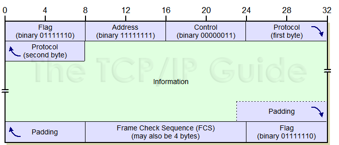
Figure 32: PPP General Frame Format
All PPP frames are built upon the general format shown above. The first three bytes are fixed in value, followed by a two-byte Protocol field that indicates the frame type. The variable-lengthInformation field is formatted in a variety of ways, depending on the PPP frame type. Padding may be applied to the frame, which concludes with an FCS field of either 2 or 4 bytes (2 bytes shown here) and a trailing Flag value of 0x7E. See Figure 33 for an example of how this format is applied Figure 33: Sample PPP Data Frame This sample PPP data frame has a value of 0x0021 in the Protocol field, indicating it is an IP datagram (though the actual data is made up and not a real IP message.) Protocol Field Ranges The Protocol field is the main “frame type” indicator for the device receiving the frame. For data frames this is normally the network-layer protocol that created the datagram, and for control frames, the PPP protocol that created the control message. In the case of protocols that modify data such as whencompression (CCP) or encryption (ECP) are used, this field identifies the data as being either compressed or encrypted, and the original Protocol value is extracted after the Information field is decompressed/decrypted. There are dozens of network-layer protocols and PPP control protocols, and a correspondingly large number of Protocol values The main PPP standard defines four ranges for organizing these values, as shown in Table 33. Table 33: PPP Protocol Field Ranges Protocol Field Range (hexadecimal) Description 0000 - 3FFF Encapsulated network layer datagrams that have an associated Network Control Protocol (NCP). In this case, control frames from the corresponding NCP use a Protocol field value that is computed by adding “8” to the first octet of the network layer Protocol value. For example, for IP the Protocol value is 0021, and control frames from the IP Control Protocol (IPCP) use Protocol value 8021. 4000 - 7FFF Encapsulated datagrams from “low-volume” protocols. These are protocols that do not have an associated NCP. 8000 - BFFF Network Control Protocol (NCP) control frames that correspond to the network layer Protocol values in the 0000-3FFF range. C000 - FFFF Control frames used by LCP and LCP support protocols such as PAP and CHAP. Some miscellaneous protocol values are included here as well. The standard also specifies that the Protocol value must be assigned so that the first octet is even, and the second octet is odd. So, for example, 0x0021 is a valid value but 0x0121 and 0x0120 are not. (The reason for this will become apparent shortly). There are also certain blocks that are reserved and not used. Protocol Field Values The full list of PPP Protocol values is maintained by the Internet Assigned Numbers Authority (IANA) along with all the other different reserved numbers for Internet standards. Table 34 shows some of the more common values: Table 34: Common Protocols Carried In PPP Frames and Protocol Field Values Protocol Type Protocol Field Value (hex) Protocol Encapsulated Network Layer Datagrams 0021 Internet Protocol version 4 (IPv4) 0023 OSI Network Layer 0029 Appletalk 002B Novell Internetworking Packet Exchange (IPX) 003D PPP Multilink Protocol (MP) Fragment 003F NetBIOS Frames (NBF/NetBEUI) 004D IBM Systems Network Architecture (SNA) 0053 Encrypted Data (using ECP and a PPP encryption algorithm) 0055 Individual-Link Encrypted Data under PPP Multilink 0057 Internet Protocol version 6 (IPv6) 00FB Individual-Link Compressed Data under PPP Multilink 00FD Compressed Data (using CCP and a PPP compression algorithm) Low-Volume Encapsulated Protocols 4003 CDPD Mobile Network Registration Protocol 4025 Fibre Channel Network Control Protocol (NCP) Control Frames 8021 PPP Internet Protocol Control Protocol 8023 PPP OSI Network Layer Control Protocol 8029 PPP Appletalk Control Protocol 802B PPP IPX Control Protocol 803F PPP NetBIOS Frames Control Protocol 804D PPP SNA Control Protocol 8057 PPP IPv6 Control Protocol LCP and Other Control Frames C021 PPP Link Control Protocol (LCP) C023 PPP Password Authentication Protocol (PAP) C025 PPP Link Quality Report (LQR) C02B PPP Bandwidth Allocation Control Protocol (BACP) C02D PPP Bandwidth Allocation Protocol (BAP) C223 PPP Challenge Handshake Authentication Protocol (CHAP) PPP Field Compression PPP uses the HDLC basic framing structure, which includes two fields that are needed in HDLC but not in PPP due to how the latter operates: the Addressand Control fields. Why bother sending two bytes that have the same value for every frame and aren't used for anything? Originally they were maintained for compatibility, but this reduces efficiency. To avoid wasting two bytes in every frame, it is possible during initial link setup using LCP for the two devices on the link to negotiate a feature calledAddress and Control Field Compression (ACFC) using the LCP option by that same name. When enabled, this feature simply causes these two fields not to be sent for most PPP frames (but not LCP control frames.) In fact, the feature would be better named “Address and Control Field Suppression” because the fields are just suppressed: compressed down to nothing. Now, even when devices agree to use field compression, they must still be capable of receiving both “compressed” and “uncompressed” frames. They differentiate one from the other by looking at the first two bytes after the initial Flag field. If they contain the value 0xFF03, they must be the Address andControl fields; otherwise, those fields were suppressed. (The value 0xFF03 is not a valid Protocol field value, so there is no chance of ambiguity.) Similarly, it is also possible for the two devices on the link to negotiate compression of the Protocol field, so it takes only one byte instead of two. This is done generally by dropping the first byte if it is zero, a process called Protocol Field Compression (PFC). Recall that the first byte must be even and the second odd. Thus, a receiving device examines the evenness of the first byte of the Protocol field in each frame. If it is odd, this means that a leading byte of zeroes in the Protocol field has been suppressed, because the first byte of a full two-byte Protocol value must be even.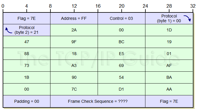
This range also includes several values used for specially-processed encapsulated datagrams, such as when compression or encryption are employed.


No comments:
Post a Comment